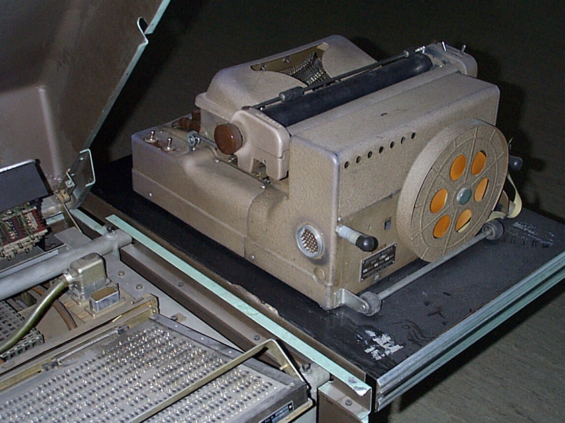
LGP-30
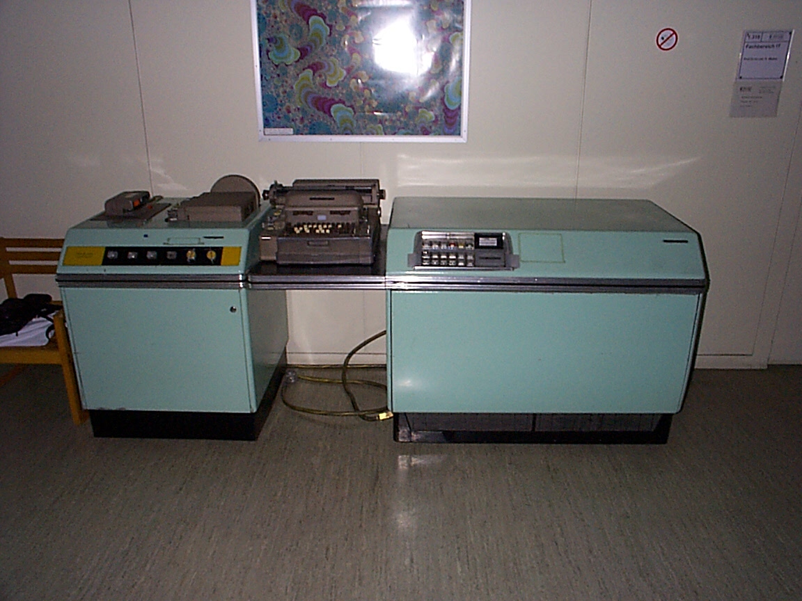
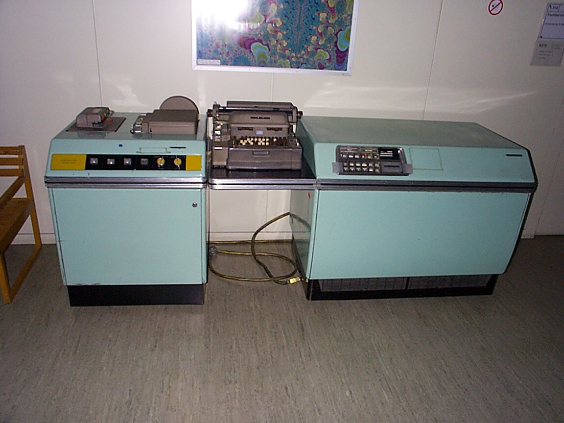
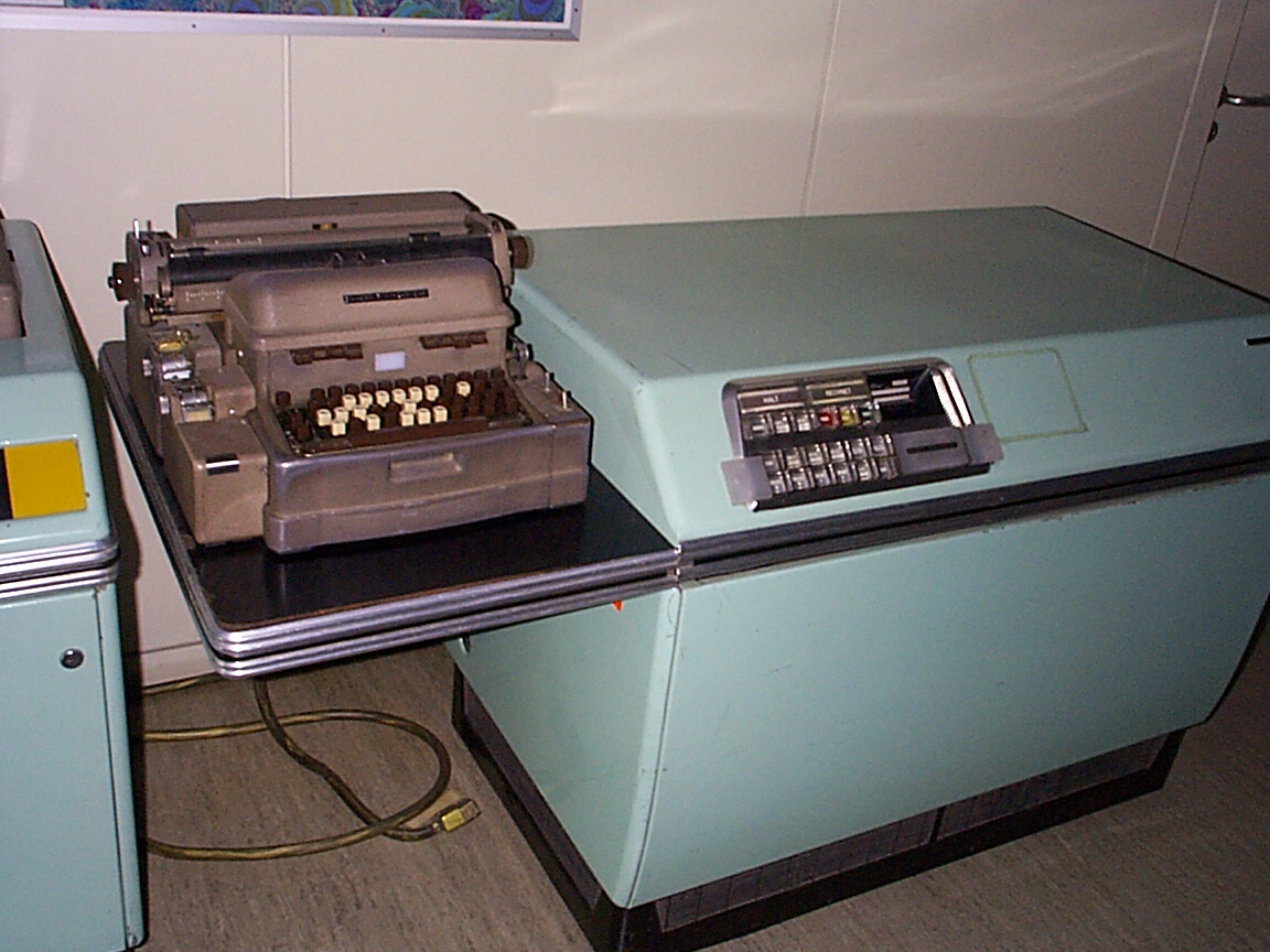
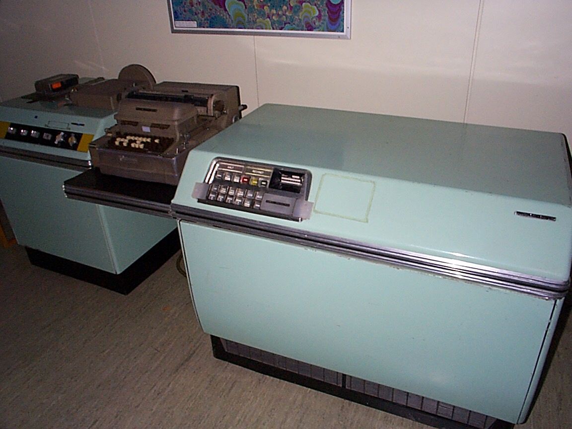
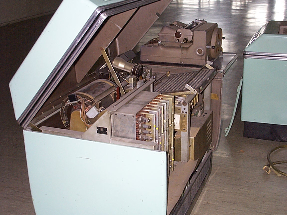
The computermuseum owns an LGP-30 since november 24, 1999. Technically this computer of the first generation is in a very good original condition. The only part that is not original is the paint. Somebody painted it mint green sometime...
Miscellaneous
The LGP-30 was built from 1957, first in the USA by Librascope/General Precision or Royal McBee. Since 1958 it was built in license from the German firm Schoppe&Faeser in Minden (Westphalia) for the European market. The LGP-30 in the museum is a German product and has the serial number 4.
In the company brochure are noted some special features like easy transportability due to the low weight of only 384 kg as well as the fact that no air conditioned room is needed because the power consumption is only 1.5kW.
One more note to the weight: In order to pull it from the pallet in its new domicile I only needed to recruit five more "volunteering" students from the computer pool next door. Together with the two students who helped me since Esslingen, we were eight people in total, so everyone had only 45 kg to move.
Technological overview
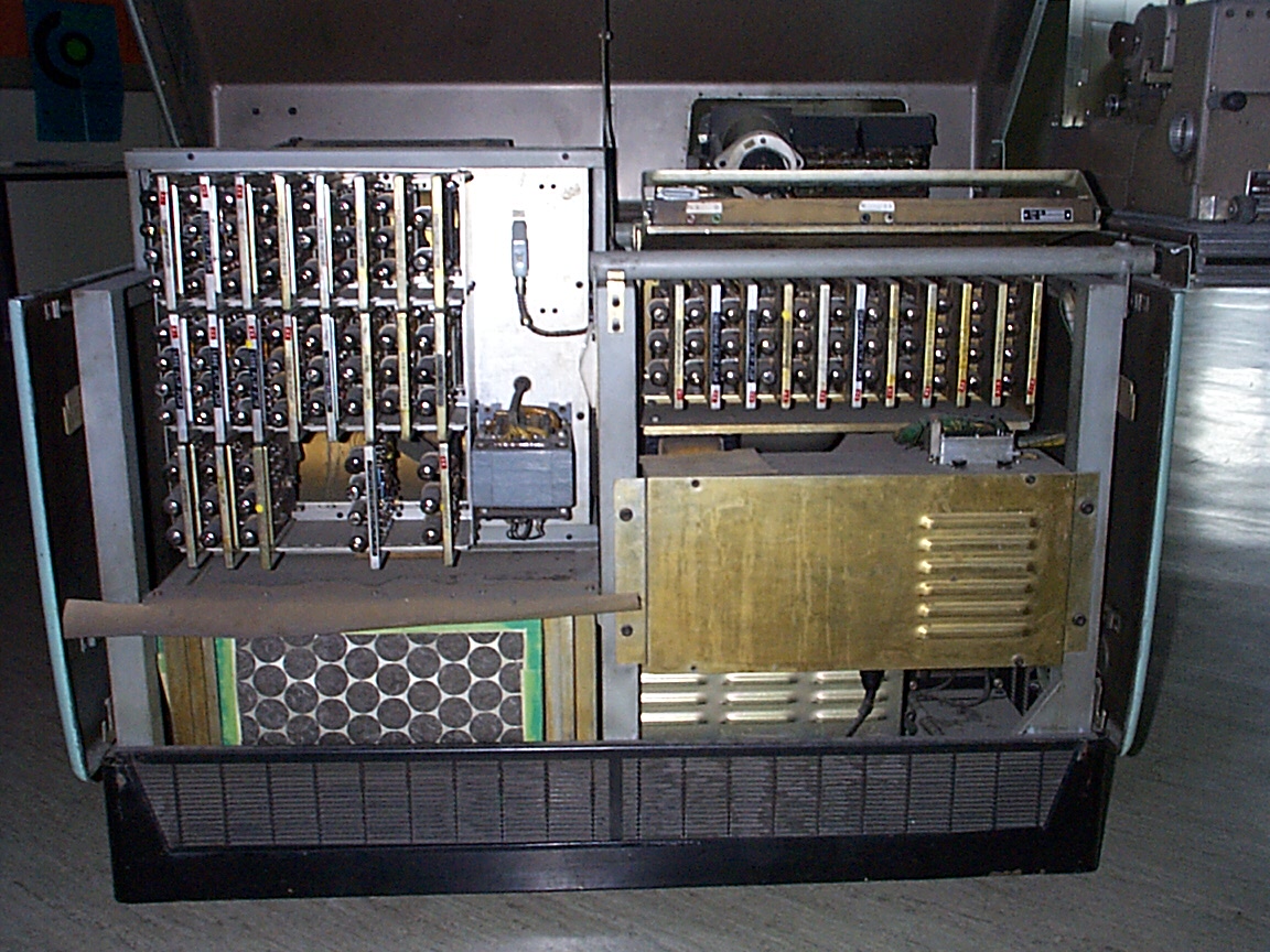
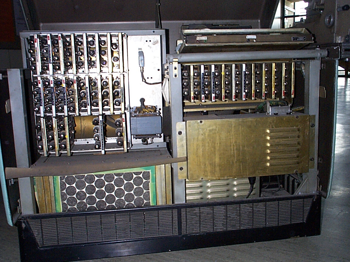
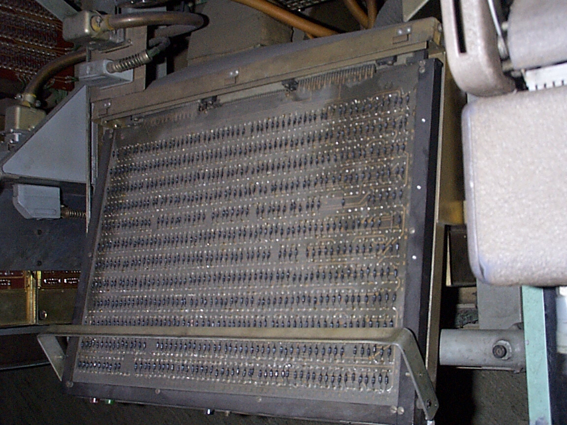
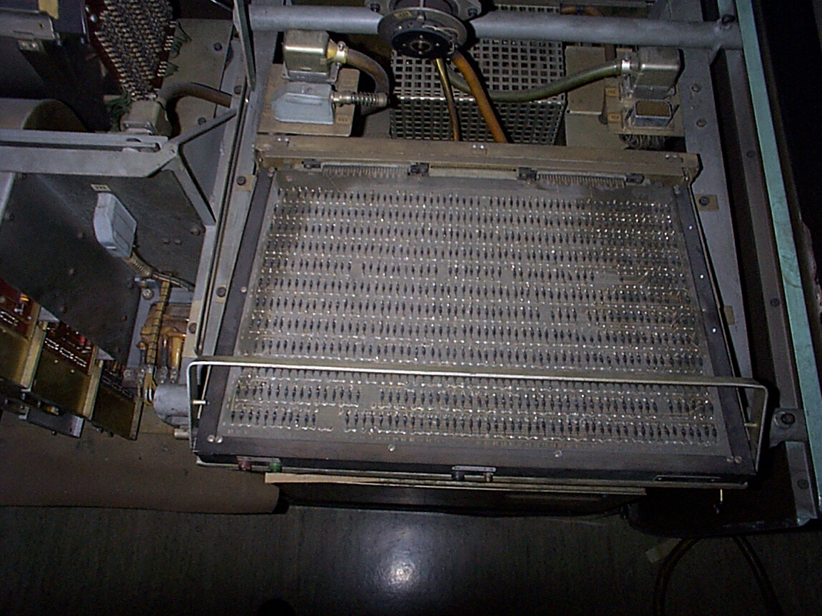
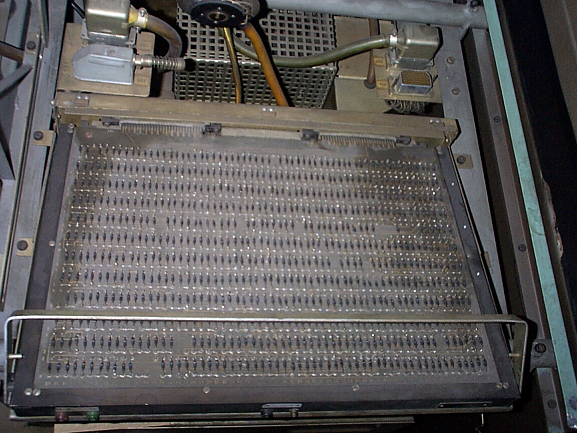
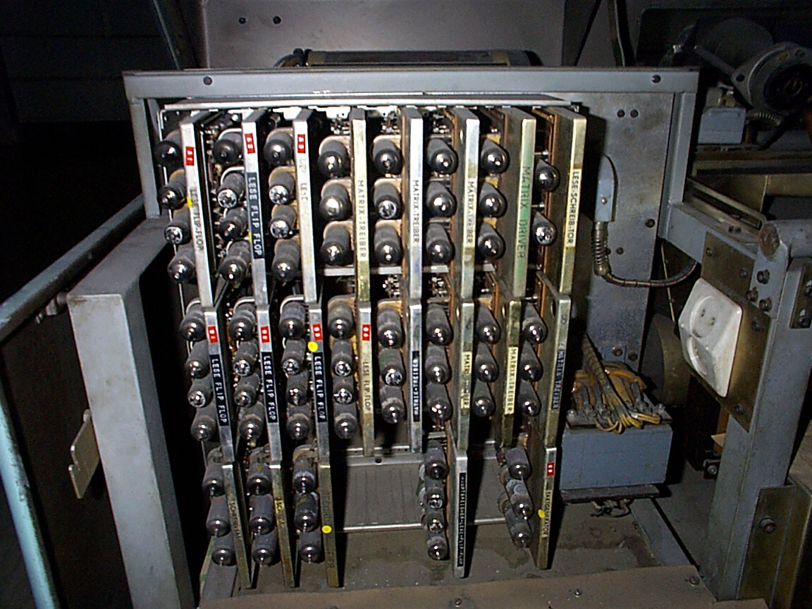
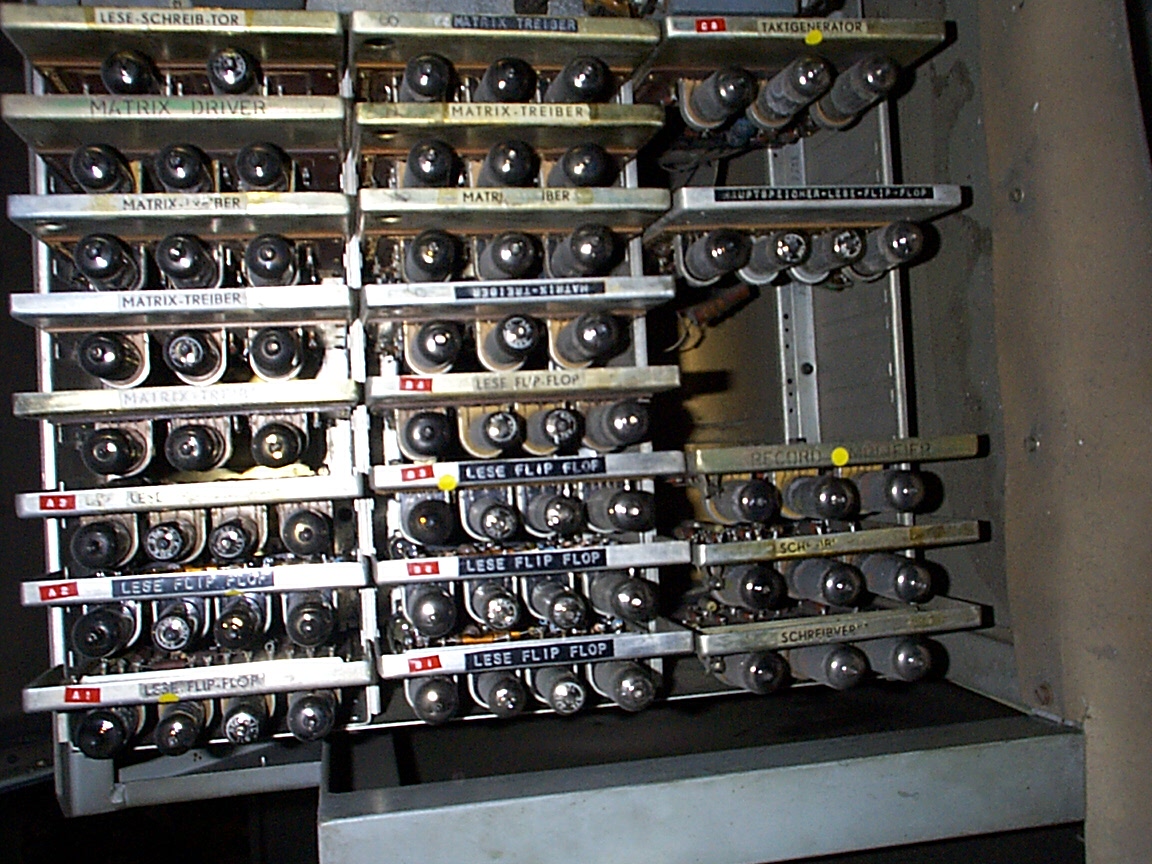
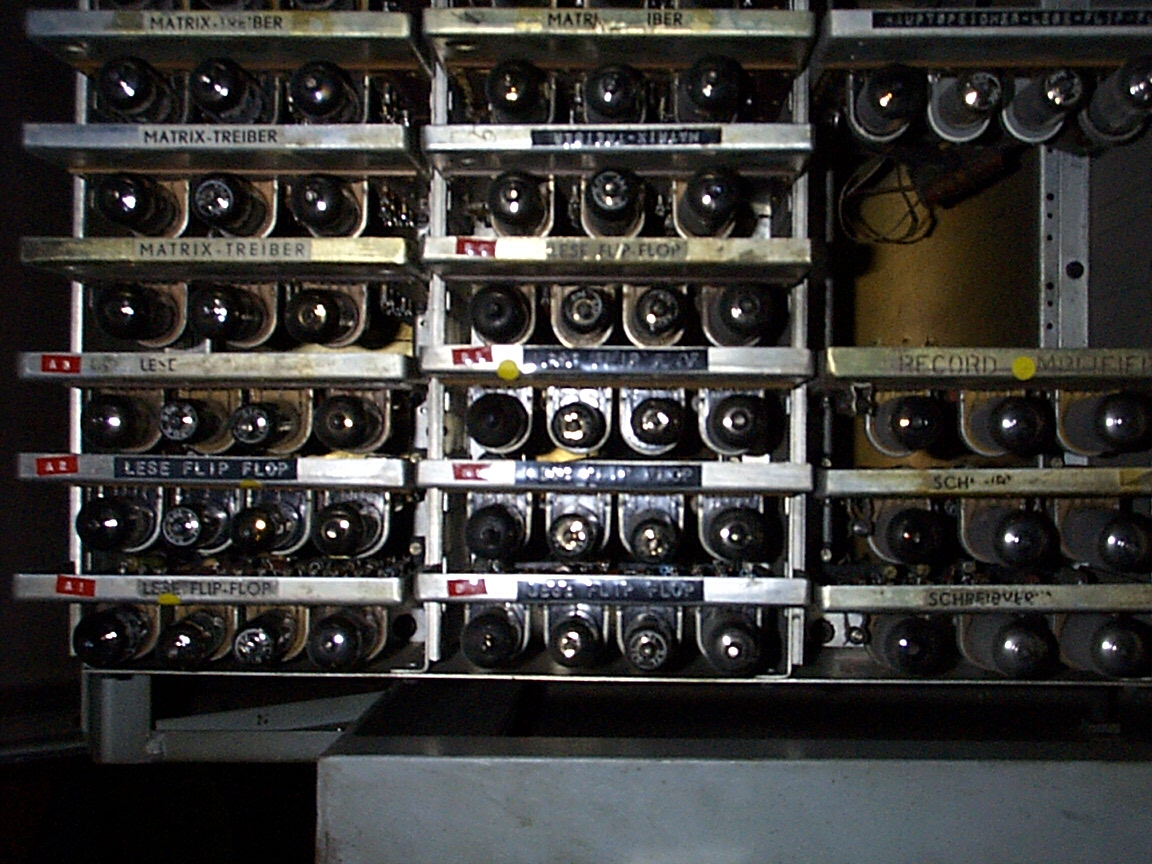
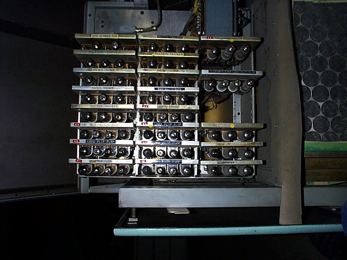
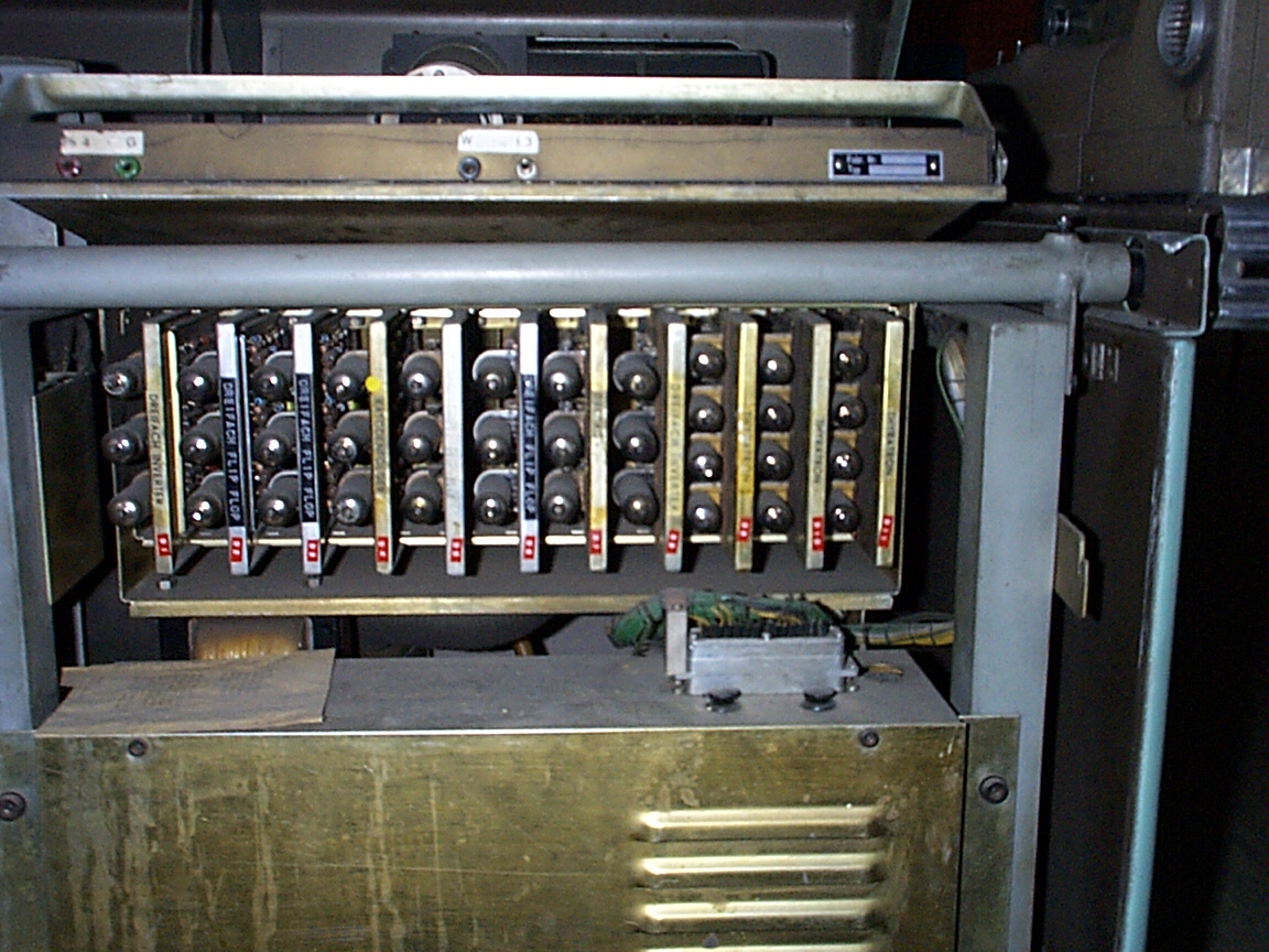
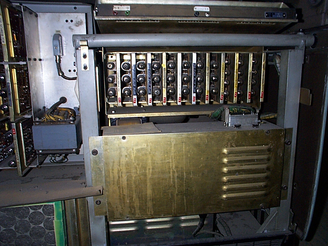
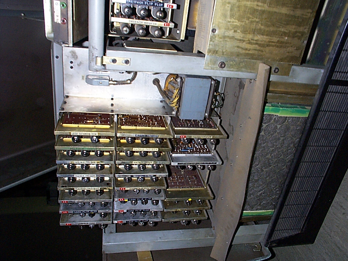
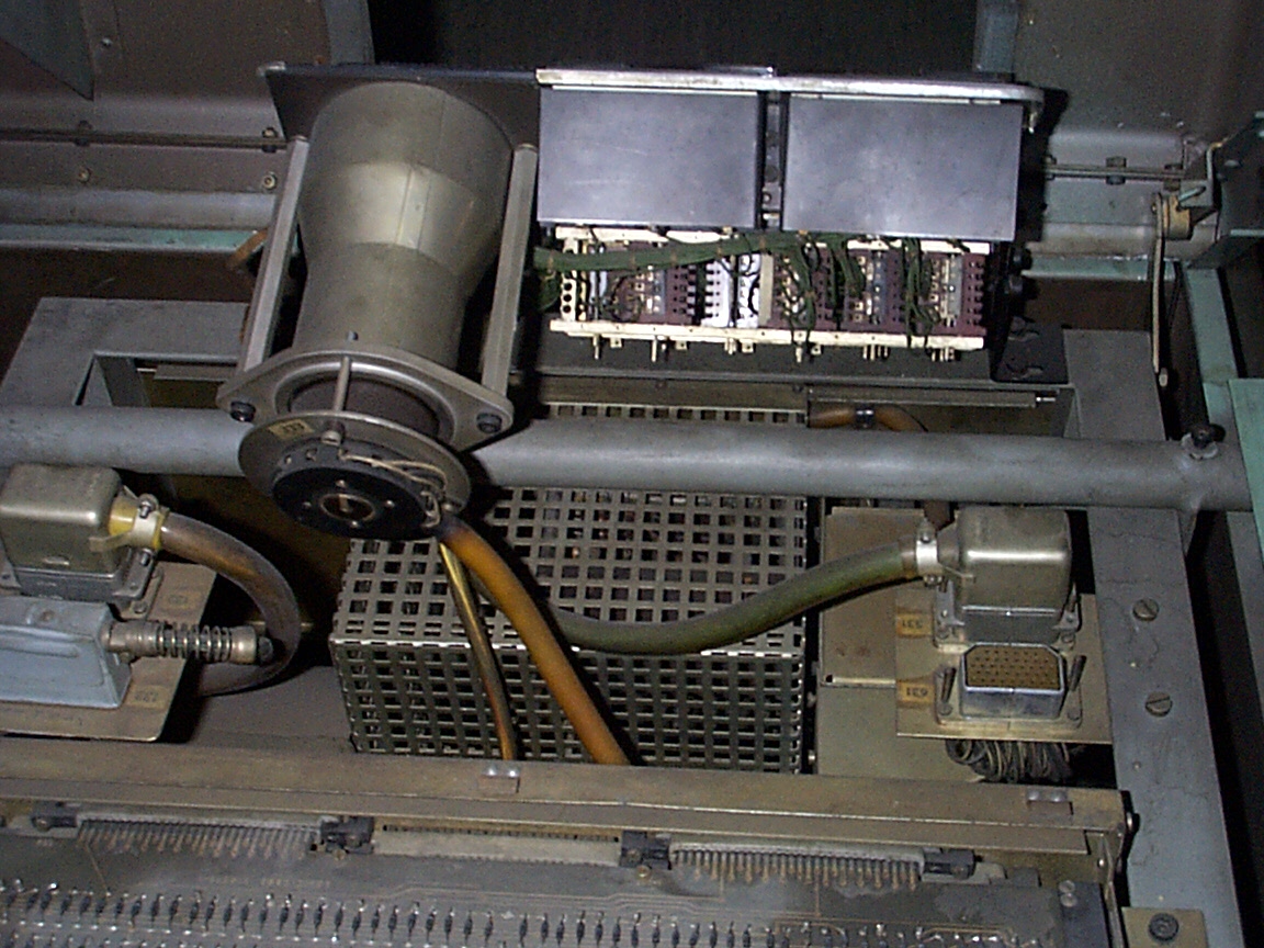
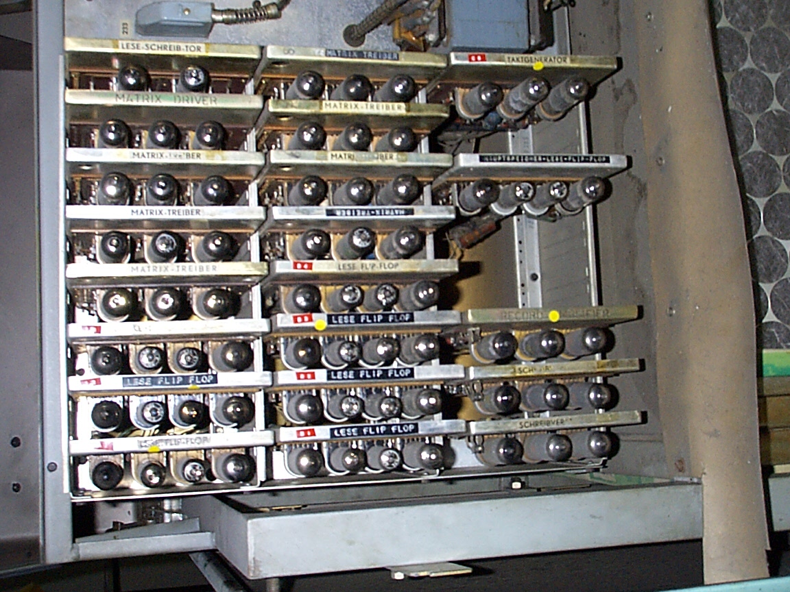
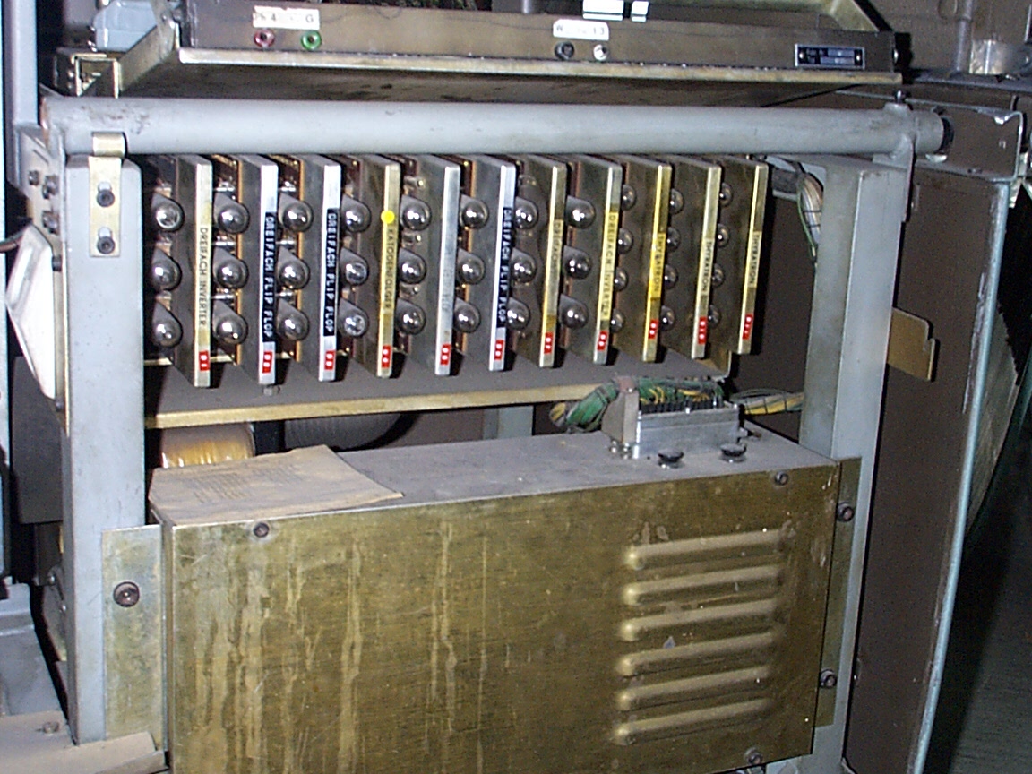
The computer is equipped with 113 tubes and has, as noted above, a power consumption of 1.5kW.
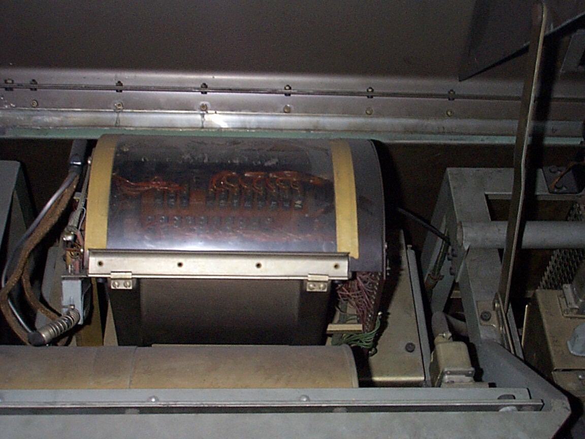
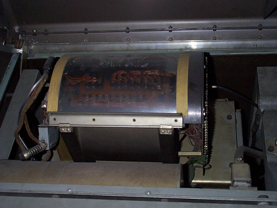
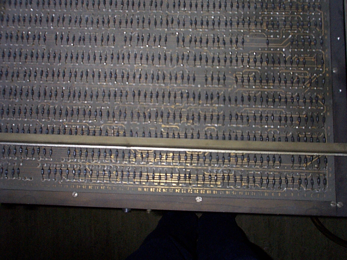
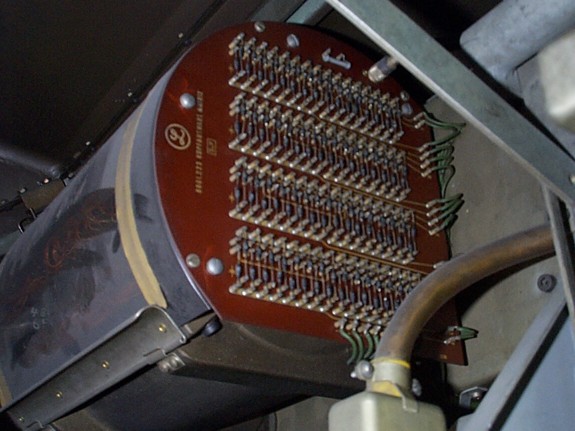
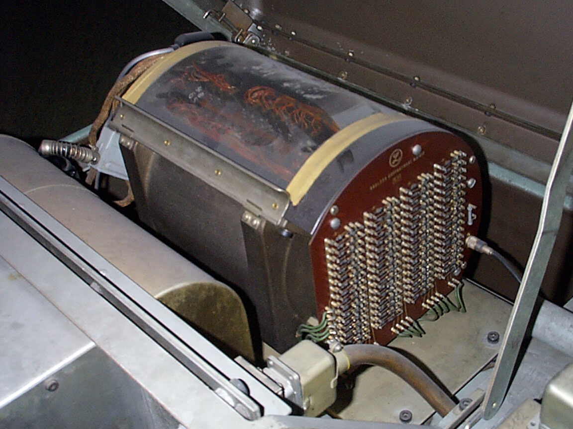
As main memory serves a magnetic drum with 4096 words at 32 bits each. The computer is a bit-serial architecture and all registers are on the drum, too:
The accumulator, the program counter and the instruction register.
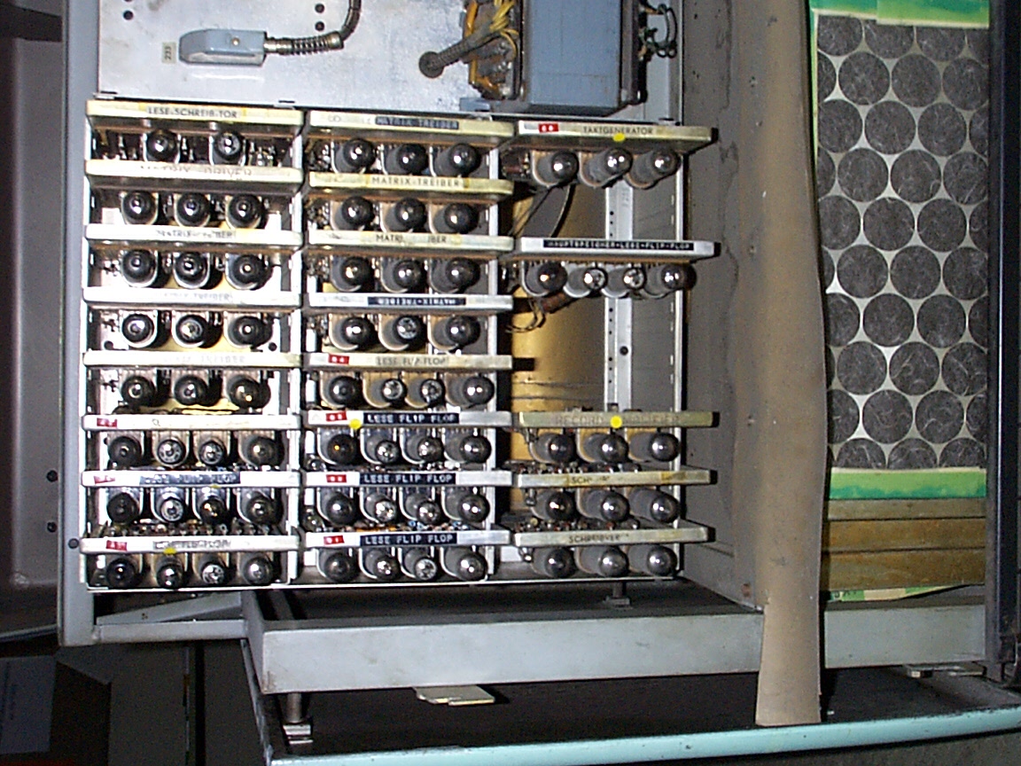
This makes it possible to build a CPU with only 24 tubes that realise 15 flip-flops, 6 cathode followers and 6 inverters. The remaining tubes are needed to control the magnetic drum and the Flexowriter, for the clock generator and for the read/write amplifiers.
Instruction set
The instruction set consists of 16 instructions:
0001  B mn    Bring accumulator from memory cell mn        "Bring"
1100  H mn    Store accumulator in mn and hold             "Hold"
1101  C mn    Store accumulator in mn and clear            "Clear"
1110  A mn    Add                                          "Add"
1111  S mn    Subtract                                     "Subtract"
0111  M mn    Multipliy, keep top half                     "Multiply"
0110  N mn    Multipliy, keep bottom half
0101  D mn    Divide                                       "Divide"
1001  E mn    Logical product (AND)                        "Extract"
1010  U mn    Unconditional jump to mn                     "Unconditional jump"
1011  T mn    Jump to mn if accumulator is negative        "Test and jump"
0010  Y mn    Replace address part
0011  R mn    Store return address                         "Return"
0100  I       Input                                        "Input"
1000  P m     Print symbol denoted by m                    "Print"
0000  Z m     Halt if the breakpoint switch associated with
              m is not depressed.
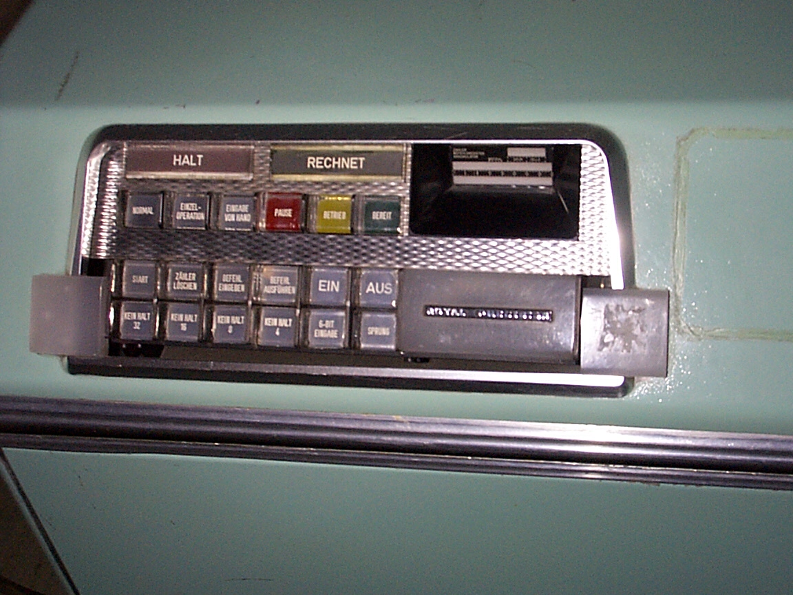
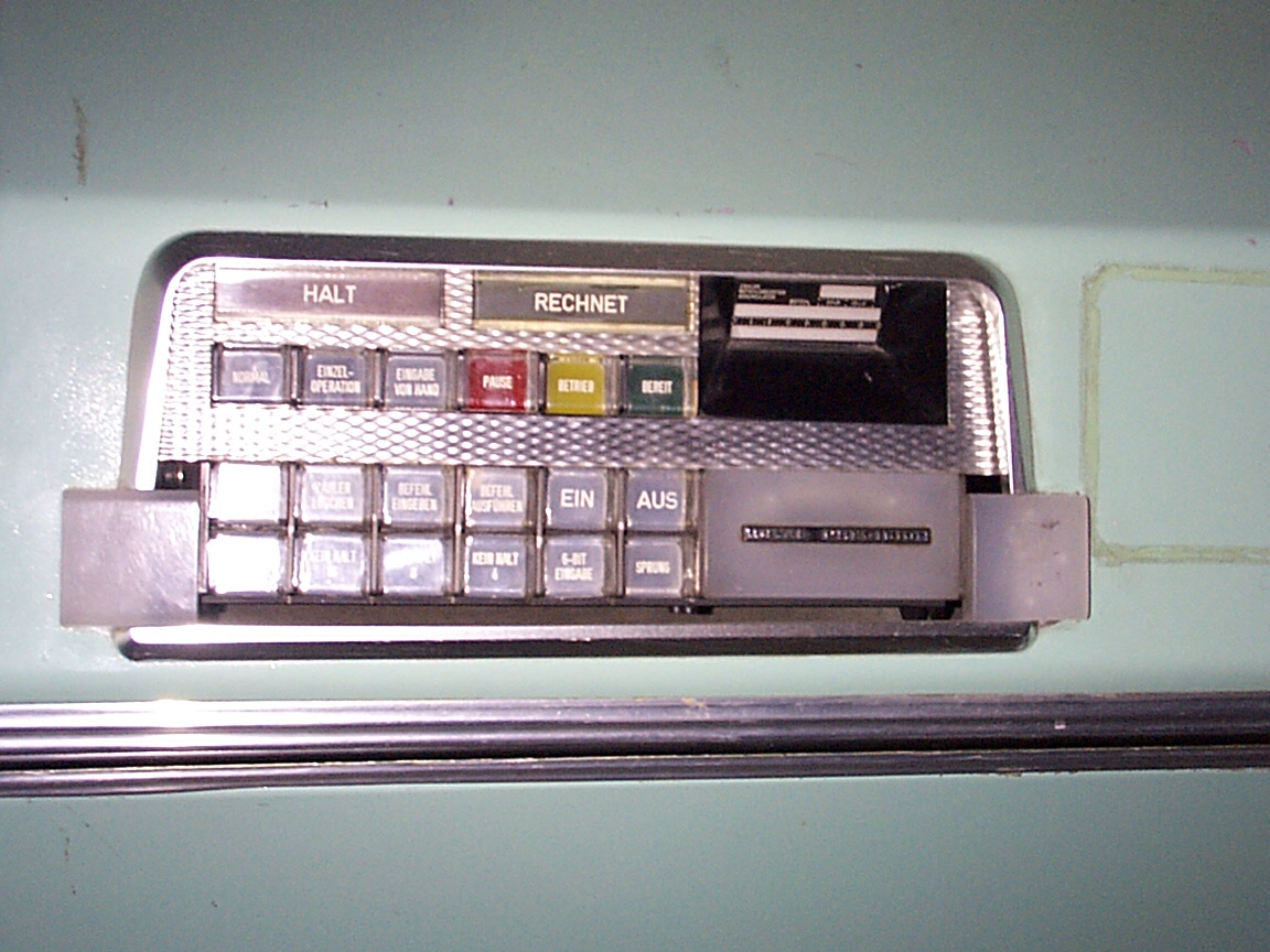
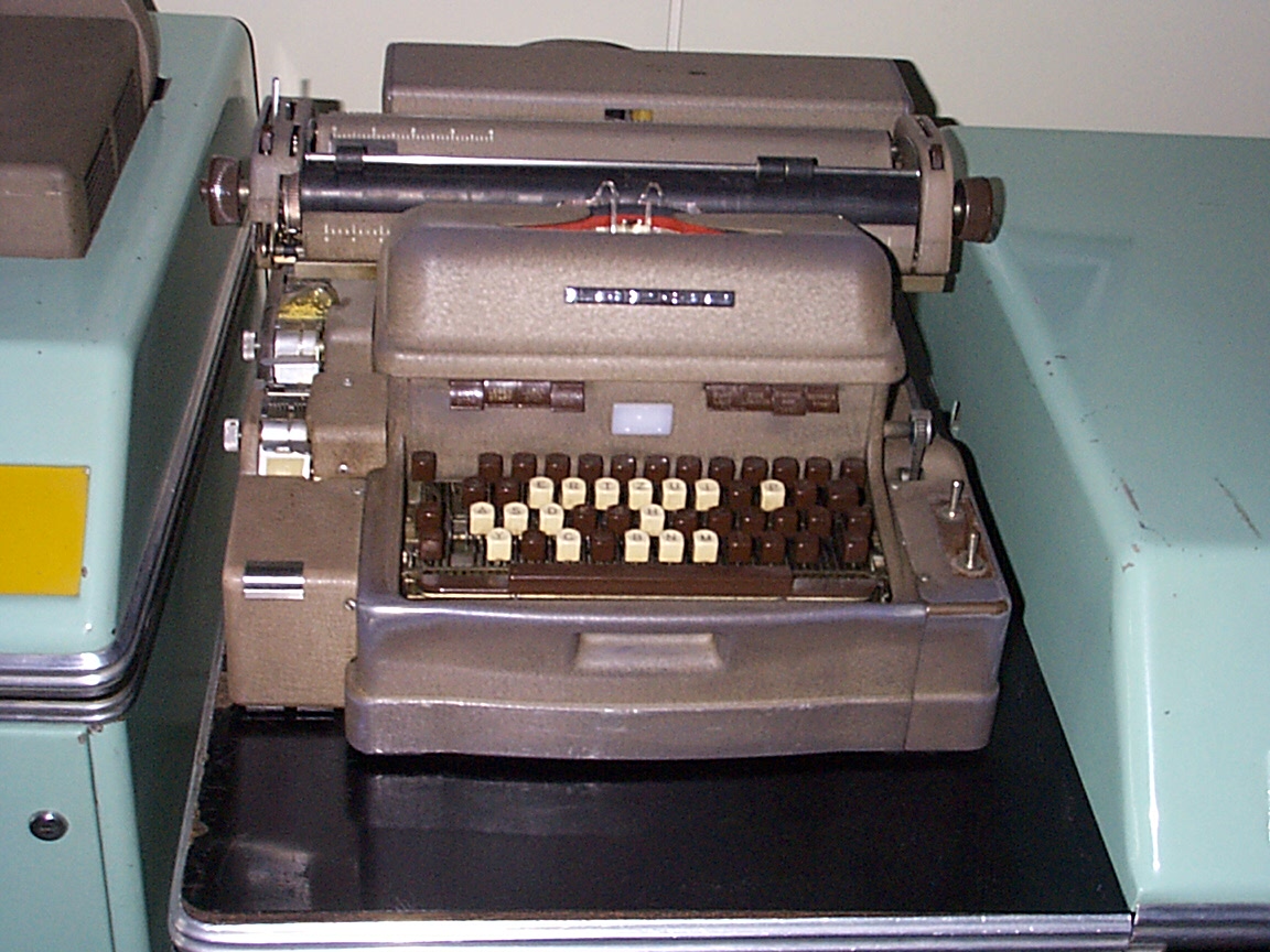
Each opcode is represented by a letter. The binary code of the instruction corresponds to the code of the letter of the flexowriter with the two most significant bits being ignored. The ASCII wasn't invented, yet. The keyboard on the picture shows 16 white keys: these are the letters assigned to an opcode.
The address part mn of the instruction consists of two parts:
m is the track number (6 bits)
n is the cell (or sector) number (6 bits)
Logically the address space is homogeneous (4096 words, 12 bit address), but the LGP-30 being a magnetic drum computer has no random access memory in its original sense. Due to the division of the address in two parts the programmer was always reminded to put the variable of the relating instruction wisely in memory so that it appeared as soon as possible after the instruction. In the worst case the program has to wait one complete drum revolution until the variable can be read.