All display output is done on a builtin 5" screen
(b&w) and additionally on an external Monitor if one is attached.
It can display a total of 1024 characters organized in 16 lines at 64
characters. Each text line is made up of 12 display lines with the top
8 for the characters, the bottom 4 are always blank (see
Screen organization).
Only the characters stored in a 2048x16 ROS can be displayed.
Some repair hints:
When switching on the machine the heater filament of the picture tube
will glow very bright for a short time and continue to glow red and dim.
If the screen remains blank you should check the brightness control at the
front panel and the brightness preset potentiometer on the display PCB.
You should also check for a horizontal sync signal as it is used to generate
the high voltage for the tube in conjunction with the HV transformer and
the switching transistor. If the HV is missing a defective graphics adapter
or processor card can be the cause because the adapter has to be initialized
first before any sync signals are generated. If an external monitor works
fine the fault must be located on the display PCB.
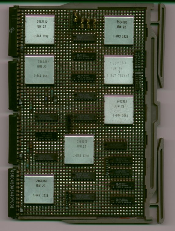
The graphics adapter is located on Card G2.
The display and the piezo beeper are addressed over the Device Address Bus and controlled over the Bus Out lines: +start execute, -control strobe, -put strobe. -control strobe and -put strobe indicate valid data on the bus.
The adapter responds to address 0 and F. A command to address 0 and Bus Out bit 0 load the jumper information into the World Trade Latch. This ist done on powerup and reset, too. This information is used by the ROS address generator to display the 12 different language characters. Upon initializing the adapter a command to address F with active Bus Out bit 4 is issued to reset the beeper and activate the display.
The graphics adapter gets its data over the Read Data Bus via Cycle Steal. The generated signals are then sent to the screen. Three signals drive the internal screen and one of them /+monitor composite video) is wired to the BNC at the rear for external monitors.
The 8 bit wide characters are stored as a pattern of seven different bits followed by a 0-bit in a 2048x16 display ROS (character generator). These 8 bits are loaded along with two 0 padding bits into a 10 bit shift register. The address of the 8 bit pattern is based on the Display Data register that contains the current character and the character row counter that counts the current display row within a character.
When the electron beam starts in the top left corner the three counters (character column, character row and display row) are reset to 0. Information about the character column and row counters are put on the Storage Address bus together with the states of the DISPLAY REGISTERS and L32-64-R32 switches.
The first two bytes are transferred from the RWS into the Display Data
register. Since the two (character) counters are zero the even byte selects
the first 8-bit line from the 2048x16 ROS that is transferred into the
shift register.
The 10 bits are shifted out serially and are used to switch the beam between
bright and dark.
The character counter is then incremented by 1.
The odd byte selects the next character pattern. After the row of the second
character has been displayed the character counter is incremented by 1.
Now the counter value is even again so the next two characters are read from
RWS. This procedure is repeated for all 64 characters on a line.
Now one character row has been completed; the character counter is reset to zero,
the address bus to the base address and the character row counter gets 1.
This entire procedure is repeated for a complete text line.
When the character row counter gets 12 it is reset to zero and the text line counter is incremented by 1. The base address is increased by 64 to read the next text line.
After the whole picture has been displayed the electron beam jumps back to its origin; meanwhile the counters continue to count. After that everything starts from the beginning.
When displaying black characters on a white background the video signal is gated to the cathode. At each position where information should be displayed the beam is blanked. Therefore without information the screen is completely white.
With White characters on a black background the +machine video signal blanks the beam except at those areas where information should be displayed. So the screen is normally black without information.
The signal -external vertical sync goes to the display PCB and is used for vertical synchronization. Without this signal the picture rolls vertically. The +external horizontal sync is similar and drives the horizontal synchronization circuitry. Without this signal the screen remains dark (no HT and no heater).
Both the graphics adapter and the processor access the RWS over the Storage Read/Write bus. Access is controlled with the Cycle Steal lines.
The -display request line is used by the adapter to request a Cycle Steal if it is ready to fetch two character bytes. The processor then activates its -stolen cycle next line and -display request is reset so that at most every second cycle can be "stolen".
During this cycle the processor asserts the -stolen cycle line and puts the two addressed bytes onto the bus. This also gates the data from the bus into the Display register on the adapter.
Micro instructions can be executed faster without Cycle Steal. Therefore an instruction can control the I/O display off line to inhibit Cycle Steal. This turns off the screen and turns on the IN PROCESS lamp.
The I/O lines from the adapter to RWS consist of the Storage Read/Write (input) bus and the Storage Address (output) bus (see Data flow diagram and Internal structure).
The data from RWS is buffered two times by the Display Data register and the character register. The data is gated into the data register at clock time MCC3 and MCC4 with active -stolen cycle line. The lines +C4 powered and +C5 powered gate the data into the character register.