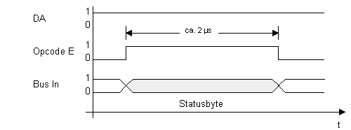
Status information should inform the processor about the current state of the device adapter in order to perform the right actions. Depending on the kind of the adapter only a single byte value may exist for status information or several bytes as with the printer adapter. The first status byte is put onto the bus when a selected adapter sees an asserted Opcode E line. This is true for machine instructions with the opcode ExyF (thus the signal name).

For the second byte IBM chose different ways.
The printer adapter decides which status byte is requested by looking
at the register number into which the byte is to be transfered. It is to
be noted that the processor puts the register number onto the Bus Out lines
for each device instruction. Status byte 1 is selected for even register numbers
and byte 2 for odd numbers. Both bytes are read with the ExyF opcode.
The diskette adapter transfers the second byte (the Access Sense byte)
like an ordinary data byte whenever the device address lines select the
diskette adapter. Opcode E has to be 0, IRQ2 must be deasserted and the
adapter has to be in Access Mode to actually read the second status byte
instead of a data byte. This is done with the 0xyE opcode (GETB). It is
a mystery why IBM did it this way.
Data from a diskette can only be transferred to the processor after eight
single bits have been read from the surface and assembled into a byte.
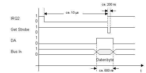
After that the IRQ2 line is asserted (0) to signal the processor that there
is a new byte to fetch from the adapter. This works independently from device
addressing as it is a real interrupt mechanism.
The response from the processor to this interrupt is to put the device
address lines onto the bus and to read the data byte. Reading automatically
resets the IRQ2 line (1). The Get Strobe impulse is always generated by
the 0xyE opcode (GETB) to tell the adapter that a data byte has sucessfully
been read.
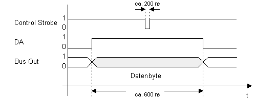
A command is sent to an adapter by putting the device address along with the command byte onto the bus followed by a Control Strobe impulse that instructs the adapter to store the value of the Bus Out lines into its command register and to execute the command. A command can be sent at any time no matter of the current state of the interrupt line or of the adapter.
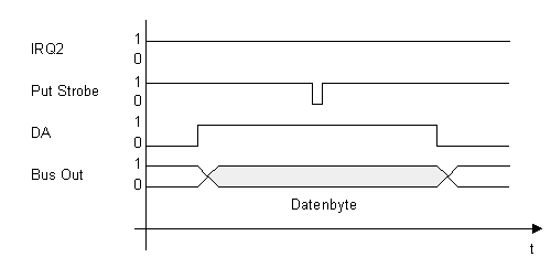
Data bytes are transfered nearly the same way as command bytes. In contrary to sending a command byte a Put Strobe impulse is generated to latch the data byte into the data register or latch of the adapter. There are two situations for sending a data byte. First a data byte can be sent upon request by the adapter with an asserted IRQ2 line. In this case the Put Strobe impulse (following a PUTB instruction) resets the IRQ2 line. Another way is to send a byte without request by the adapter, i.e. without active IRQ2 line. This way is used with the diskette adapter to send a second command byte while in Access Mode.
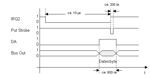
The image above shows the first case where a data transfer is done with
an active interrupt line. Putting the data byte onto the bus by the processor
automatically resets the interrupt to be ready for the next request.
Below the second case is shown. A data byte is transfered to an adapter
that did not request data with an interrupt.
