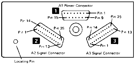


| Pin A2 | Name | Pin A3 | Name |
|---|---|---|---|
| 1 | Ground | 1 | Ground |
| 2 | -Put Strobe | 2 | +Osc/4 |
| 3 | -Control Strobe | 3 | -Interrupt Request 2 |
| 4 | -Get Strobe | 4 | +Bus Out P |
| 5 | +DA Y3 | 5 | -Bus Out 0 |
| 6 | +DA Y2 | 6 | -Bus Out 1 |
| 7 | +DA Y1 | 7 | -Bus Out 2 |
| 8 | +DA Y0 | 8 | -Bus Out 3 |
| 9 | +DA X3 | 9 | -Bus Out 4 |
| 10 | +DA X2 | 10 | -Bus Out 5 |
| 11 | +DA X1 | 11 | -Bus Out 6 |
| 12 | +DA X0 | 12 | -Bus Out 7 |
| 13 | unused | 13 | Ground |
| 14 | Ground | 14 | Ground |
| 15 | +Op Code E | 15 | unused | 16 | +Bus In P | 16 | unused |
| 17 | +Bus In 7 | 17 | unused |
| 18 | +Bus In 6 | 18 | unused |
| 19 | +Bus In 5 | 19 | unused |
| 20 | +Bus In 4 | 20 | +Start Execute Bit |
| 21 | +Bus In 3 | 21 | -Machine Check |
| 22 | +Bus In 2 | 22 | +External Horizontal Drive |
| 23 | +Bus In 1 | 23 | +Printer Clock |
| 24 | unused | 24 | unused |
| 25 | +Bus In 0 | 25 | -Power On Reset |
The +DA signales are used to address
the devices, the others for data transfers.
A '+' sign preceeding the signal name means an active high signal (+5V level)
and a '-' sign an active low signal (0V level).
Because the bus is driven with open collector drivers it has to be terminated
at the last device. For a simple solution it is sufficient to have pullup
resistors to +5V of about 300 ohms to all output lines.
The terminators are also needed on an IBM 5120!
The internal disk drives won't work without them!
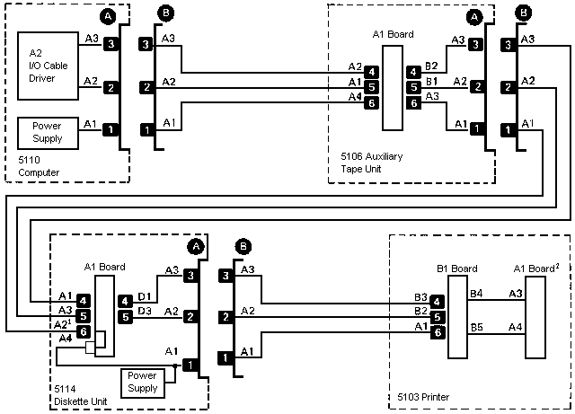
Therefore a terminator box is supplied by IBM that can be connected
e.g. on the bus output side of an IBM 5114 if no printer is attached.
When an IBM 5103 printer is used no separate terminator is needed as the bus
will be terminated within the printer. For this reason the printer has no
bus out connectors and must always be the last device on the bus.
Please pay attention to the fact that IBM has numbered the bits from the most significant to the least significant one, i.e. bit 0 has a significance of 27 down to 20 for bit 7.
Whereas the data bus between the processor and memory is 18 bits wide data from and to I/O devices is transfered over two unidirectional 8 bit busses with parity for each bus. The Bus Out lines are for data from the processor to a device and are active low (except parity). In contrast to this data into the processor from a device is transferred over the Bus In lines that are active high. The Bus Out parity can be checked by the device adapter that may pull the Machine Check line to 0 in case of an error condition which will stop the processor ("PROCESS CHECK"). In the same way a parity bit can be provided along with the Bus In lines which should be checked by the processor. It is unknown how this parity bit is interpreted. A test revealed that the processor will work correctly if Bus In P is either not connected or pulled high. But the processor will stop at the next I/O acces as soon as this line is pulled low. It seems that the parity bit is directly connected to the Machine Check line instead of being fed into the parity checker. However [CSLM5120] map 405 shows that there is no such connection at all.