Here is a location map of the modules:
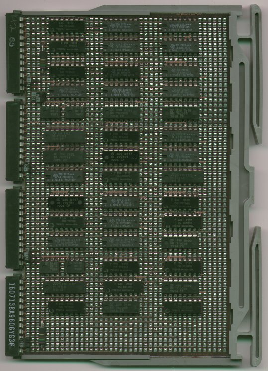
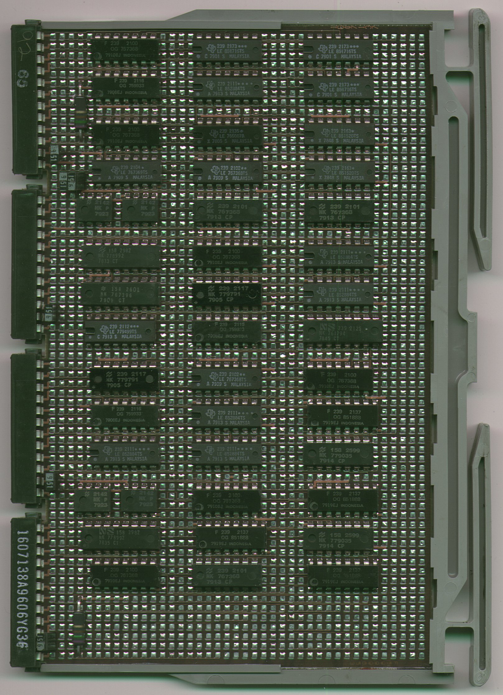
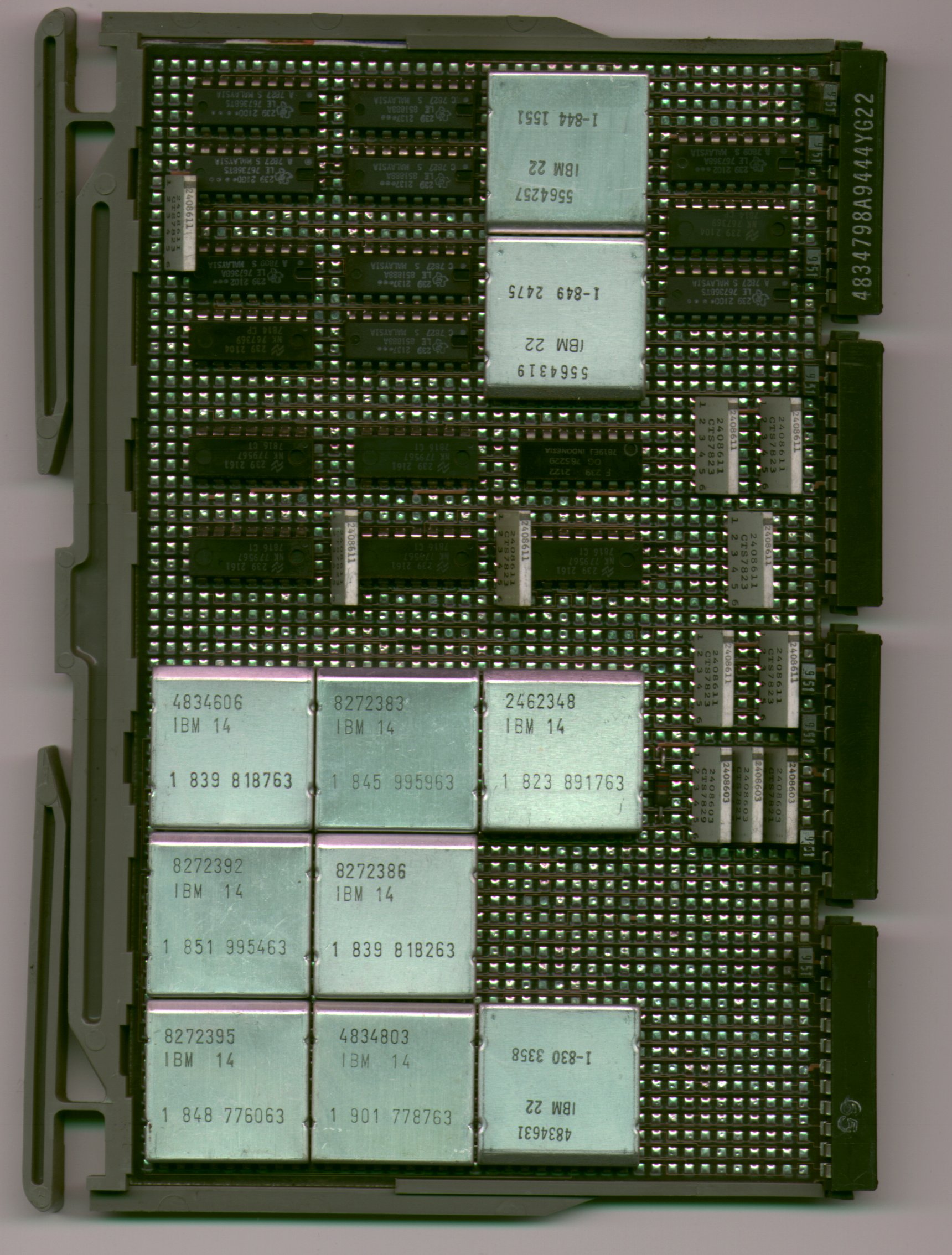
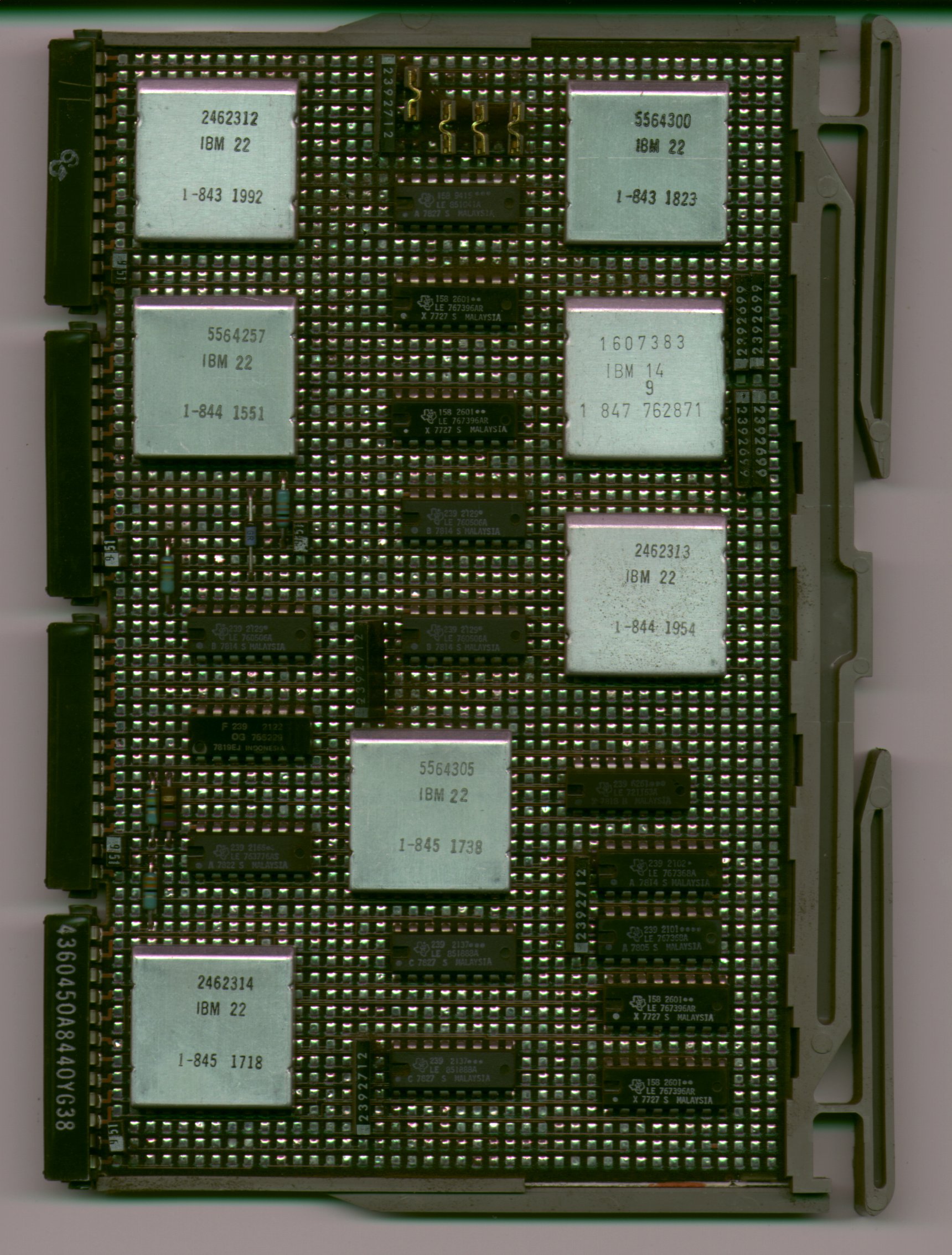
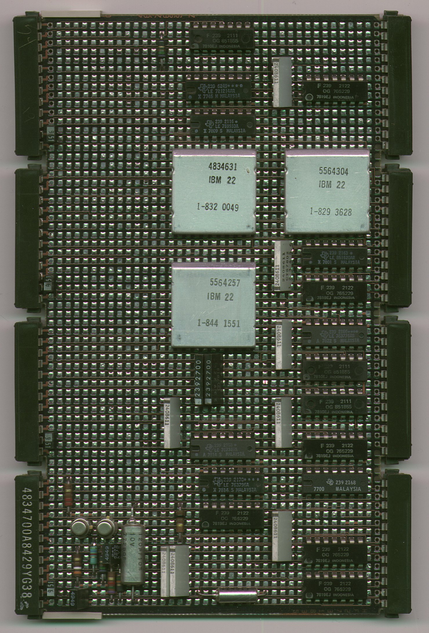
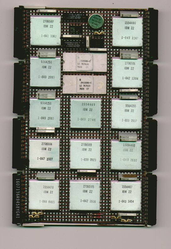
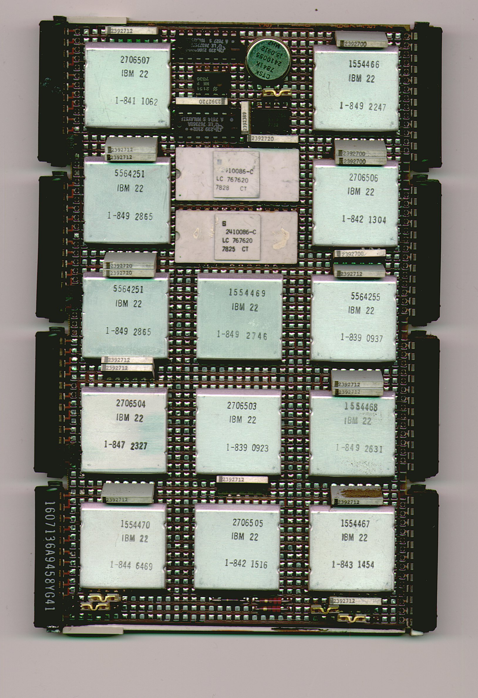
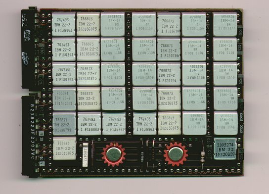
Now some pictures of the modules each in 100 dpi and 300 dpi. The smaller ones can be selected on the map above, too.
The pinouts of the connectors Y2, Y3 and Z1 are along with the description of the corresponding card.
| Y1 Cable Pin |
A1 Board Pin |
Name |
Y1 Cable Pin |
A1 Board Pin |
Name |
|---|---|---|---|---|---|
| D02 | A1D11 | +5V DC | B02 | A1D13 | +5V DC |
| D03 | A1E11 | +5V DC | B03 | A1E13 | +5V DC |
| D04 | B1A11 | +5V DC | B04 | B1A13 | +5V DC |
| D05 | B1B11 | +5V DC | B05 | B1B13 | +5V DC |
| D06 | B1C11 | GND | B06 | B1C13 | GND |
| D07 | B1D11 | GND | B07 | B1D13 | GND |
| D08 | B1E11 | GND | B08 | B1E13 | GND |
| D09 | C1A11 | GND | B09 | C1A13 | GND |
| D10 | C1B11 | GND | B10 | C1B13 | (unused) |
| D11 | C1C11 | +8,5V DC | B11 | C1C13 | +8,5V DC |
| D12 | C1D11 | +12V DC | B12 | C1D13 | +12V DC |
| D13 | C1E11 | -5V DC | B13 | C1E13 | -12V DC |
| Z2 Cable Pin |
A1 Board Pin |
Name |
Z2 Cable Pin |
A1 Board Pin |
Name |
|---|---|---|---|---|---|
| D02 | D6E02 | -EOT | B02 | D6E04 | +Tape Clock |
| D03 | E6A02 | -Erase Inactive | B03 | E6A04 | +5V dc |
| D04 | E6B02 | -BOT | B04 | E6B04 | -Forward |
| D05 | E6C02 | -Diagnostic Mode | B05 | E6C04 | -Run |
| D06 | E6D02 | -5V dc | B06 | E6D04 | -Write Enable |
| D07 | E6E02 | -LED and Erase OK | B07 | E6E04 | -Write Data |
| D08 | F6A02 | GND | B08 | F6A04 | GND |
| D09 | F6B02 | -Read Data | B09 | F6B04 | -Channel Select |
| D10 | F6C02 | -Read Clock | B10 | F6C04 | -Channel 0 Erase |
| D11 | F6D02 | +12V dc | B11 | F6D04 | -Channel 1 Erase |
| D12 | F6E02 | -Cartridge in Place | B12 | F6E04 | -Select Magnet Active |
| D13 | G6A02 | -12V dc | B13 | F6A04 | +File Protect |
| Z3 Cable Pin |
A1 Board Pin |
Name |
Z3 Cable Pin |
A1 Board Pin |
Name |
|---|---|---|---|---|---|
| D02 | H6A02 | -Reverse Display | B02 | H6A04 | +Single Instruction Switch (com) |
| D03 | H6B02 | +5V dc | B03 | H6B04 | +APL Switch |
| D04 | H6C02 | -Run Switch and Not IPL | B04 | H6C04 | -Single Instruction Switch (nc) |
| D05 | H6D02 | +Single Instruction Switch (no) | B05 | H6D04 | +In Process LED |
| D06 | H6E02 | -Display Reg | B06 | H6E04 | -Machine Video |
| D07 | J6A02 | -Normal 64 | B07 | J6A04 | -I/O Display Off |
| D08 | J6B02 | GND | B08 | J6B04 | GND |
| D09 | J6C02 | GND | B09 | J6C04 | -Machine Check LED |
| D10 | J6D02 | +Alarm On | B10 | J6D04 | -Right Select 32 |
| D11 | J6E02 | -External Horizontal Drive | B11 | J6E04 | +12V dc |
| D12 | K6A02 | -External Vertical Sync | B12 | K6A04 | (unused) |
| D13 | K6B02 | -Power On Reset Switch | B13 | K6B04 | +Monitor Video |
| Z4 Cable Pin |
A1 Board Pin |
Name |
Z4 Cable Pin |
A1 Board Pin |
Name |
|---|---|---|---|---|---|
| D02 | L6B02 | (unused) | B02 | L6B04 | (unused) |
| D03 | L6C02 | +5V dc | B03 | L6C04 | (unused) |
| D04 | L6D02 | (unused) | B04 | L6D04 | -Kbd P |
| D05 | L6E02 | (unused) | B05 | L6E04 | -Kbd O |
| D06 | M6A02 | -Kbd 1 | B06 | M6A04 | (unused) |
| D07 | M6B02 | -Power On Reset | B07 | M6B04 | -Kbd Strobe |
| D08 | M6C02 | GND | B08 | M6C04 | -Kbd 3 |
| D09 | M6D02 | +Typamatic | B09 | M6D04 | -Kbd 4 |
| D10 | M6E02 | (unused) | B10 | M6E04 | -Kbd 5 |
| D11 | N6A02 | -Keyboard Lockout | B11 | N6A04 | +8,5V dc |
| D12 | N6B02 | (unused) | B12 | N6B04 | -Kbd 7 |
| D13 | N6C02 | -Kbd 2 | B13 | N6C04 | -Kbd 6 |